Li Fi Project Circuit Diagram
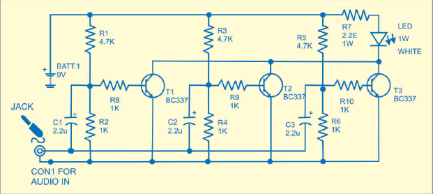
Here we are using battery to power up the leds because there is less power coming from the audio source which is not enough to power the leds. Id love to try making some circuit boards with a proper ground plane and very short traces in order to attempt to really crank up the bitrate.

Simple Li Fi Circuit Using Transistor Diy Electronics Projects
You can use a current limiting resistor series with led if you want operate the circuit at higher voltage say 12vyou can also use standard 05mm white led with current limiting resistor.
Li fi project circuit diagram. First im going to tell you in brief about lifi. It uses a li fi dongle to transmit audio signals from a source such as mobile phone and a li fi speaker with solar cells at the receiver end to receive audio signals without wires. Li fi stands for light fidelity which uses visible light as medium for data transmission.
The transmitter circuit for li fi speaker is given in fig1. The above design can be also tried using a single transistor as shown below. Otherwise its a binary zero.
The idea of li fi is to use existing light. The full form of lifi is light fidelity. So far we have understood that li fi is a method in which led is used for transmitting a high frequency content within an enclosed room which effectively transforms the led into a wireless transmitter as well as a light producing devicefor example li fi concept can be used for transmitting and receiving a music data by using an led as the light source and also a wireless music transmitter.
Fig2 shows the receiver circuit. Lifi is designed to use led light bulbs similar to those present in our homes and offices. Li fi technology is much faster as compared to the traditional wi fi technology.
Today we are going to perform an experiment on li fi. The proposed li fi dongle is connected to the audio jack output available on mobile phones. The li fi system consists of normal led light bulbs and modulating circuits.
It is capable of transmitting data up to 100 mbps. If the led is on the photo detector registers a binary one. The idea of li fi was introduced by a german physicist.
Lifi basically is a wireless communication technology which uses visible light for data transmission. The speaker circuit is made up of solar cell array to trap light signals. Circuit and working of diy li fi speaker.
Li fi circuit diagram update. Li fi is transmission of data using visible light by sending data through an led light bulb that varies in intensity faster than the human eye can follow. Transmitter circuit for li fi.
Lets clearly understand what exactly li fi technology is before going in to circuit diagram. On transmitter side we have white bright led and a battery which are connected to 35mm jack and jack will be connected to audio source. The proposed concept is illustrated in fig.
In some cases by using parallel transmission more than 10 gbps of data can also be transmitted. The transmitter circuit is made of three amplifiers.
Https Www Scirp Org Pdf Wet 2017103013270545 Pdf

How To Make Wireless Audio Transfer Circuit How To Make Lifi
Li Fi Technology In Wireless Communication Revathi Ganesan


Pdf Pc Pc Communication Using Li Fi

Li Fi Audio Transmission Through Light 7 Steps Instructables
Https Www Arpnjournals Com Jeas Research Papers Rp 2015 Jeas 0815 2357 Pdf
Http Paper Ijcsns Org 07 Book 201812 20181211 Pdf
Audio Transfer Using Li Fi Technology Electronics Maker
Project Li Fi
